Home
Hello I am Jack Stringer a photographer and motorcycle enthusiast.
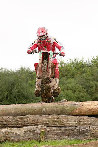
I have managed to merge both my passions photography and motorcycling. I used photograph motorcycle events, mainly off-road motorcycling. I was the Official photographer for Midwest MCC events and I did try to get to as many other events as I can including Long Distance Trials, Enduro, Hare & Hounds, Trials, Time Trials, Classic Scrambles, and the occasion Road Racing meeting.
But these days I don't do as much as I used to. Various things coincided with me needing to take a break from it. Mostly a new job that means I just don't have the time for it.
To see my photographs please visit my online gallery at http://gallery.jackstringer.co.uk